Individual assignment:
Add an output device to a microcontroller board you’ve designed and program it to do something
Introduction
Output week all about taking out signals/commands from electronics/microcontrollers and performing the task. The week’s assignment started with Niel’s class. Due to pandemic issues our lab access was limited. I decided to actuate an actuator. We have many types of actuators in markets. I did some study on rotary actuators , here mentioning only servo motors
Servo Motors
servomotor is a rotary actuator or linear actuator that allows for precise control of angular or linear position, velocity and acceleration[ wikipedia]. Other popular rotary actuators are Stepper motor, DC Motor etc, brushless motors etc. Mechanism
A typical servo motor has a small DC motor, potentiometer, and a control circuit. The motor is attached by gears to the control wheel. As the motor rotates, the potentiometer's resistance changes, so the control circuit can precisely regulate how much movement there is and in which direction
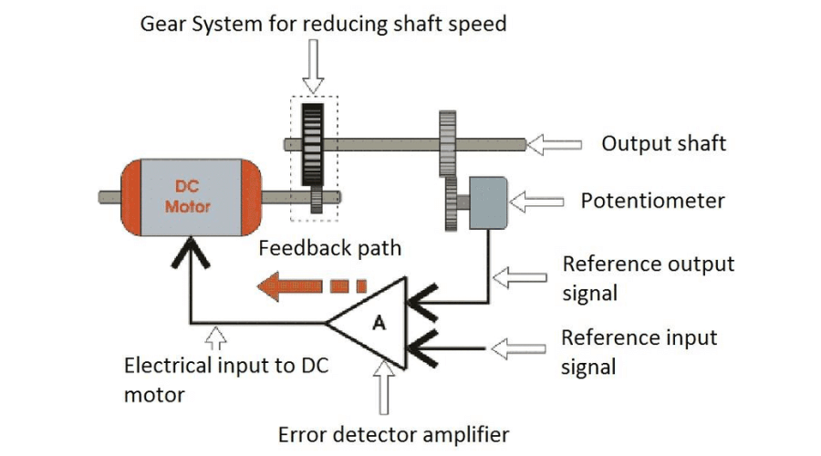
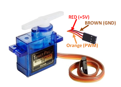
Servos are controlled by sending an electrical pulse of variable width, or pulse width modulation (PWM), through the control wire.The PWM sent to the motor determines position of the shaft,based on the duration of the pulse sent.
‣ Summary of my work
Considering my final project I decided to actuate a servo motor using a microcontroller. To do this 1. Designed a PCB with ATtiny84 using EAGLE. 2. Exported Trace images 3. Milled using Roland PCB milling machine 3. Soldered all electronic components and did a small debugging for rectifying my board’s issues. 4. Later I programmed using ARDUINO IDE. firstly programmed for one servo and secondly, programmed for two servos, both worked properly.
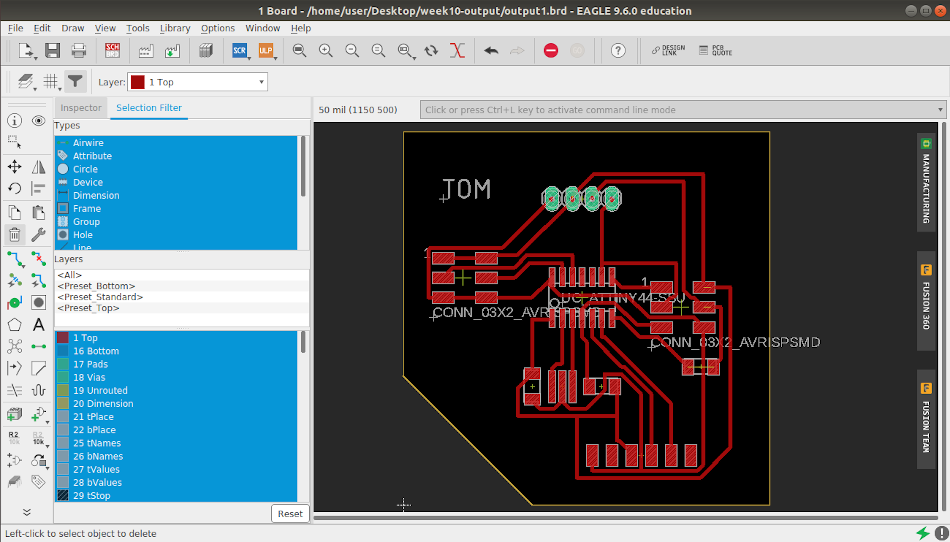
‣ PCB Designing Using EAGLE.
Since I have been using EAGLE from my week 6_Elctronic design, I never had a second thought to start PCB
designing. I referred documentation for electronic
design to do this task. ATtiny 84 has enough pins for my
purpose.
The components used are
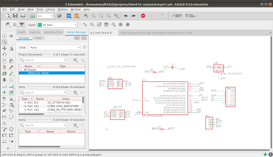
A servo motor needs 3 pins, So I used one more ISP header which has( 2x3 ) 6 pins that helps to run two or
more servos simultaneously .
This time I added a external clock of 20 Hz ( learnings from input week's mistakes)
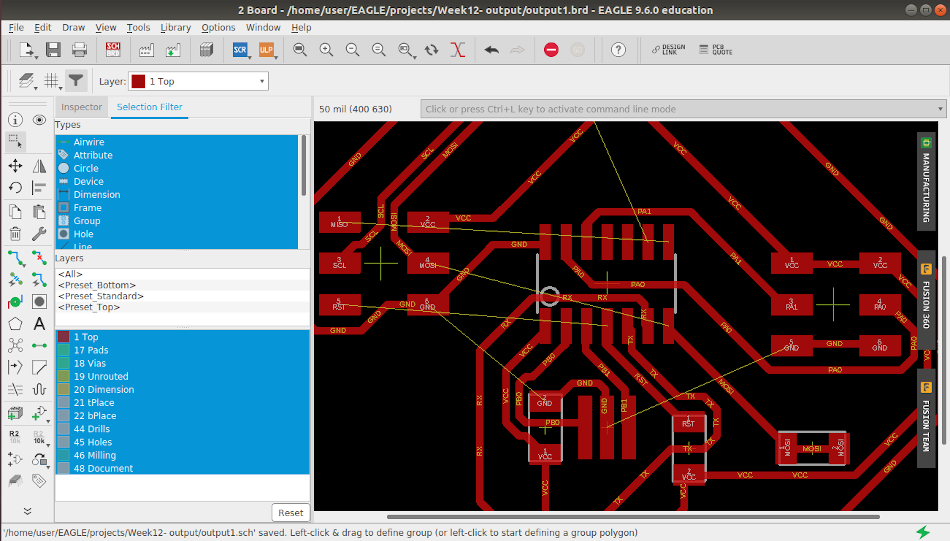
Since auto routing option in eagle could achieve less 65% ruting, I was forced to manually route the traces
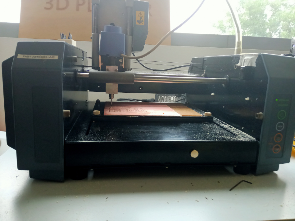
‣ PCB Milling.
For Milling PCB for output week, I followed the same steps that helped me to mill the prior week's assignments. I used MODS to communicate with Roland PCB Machine. The Milled traces have roughness, this might be due to bed unevenness and minor deformation in trace tool. So I used sandpaper to give the board a nice finish.
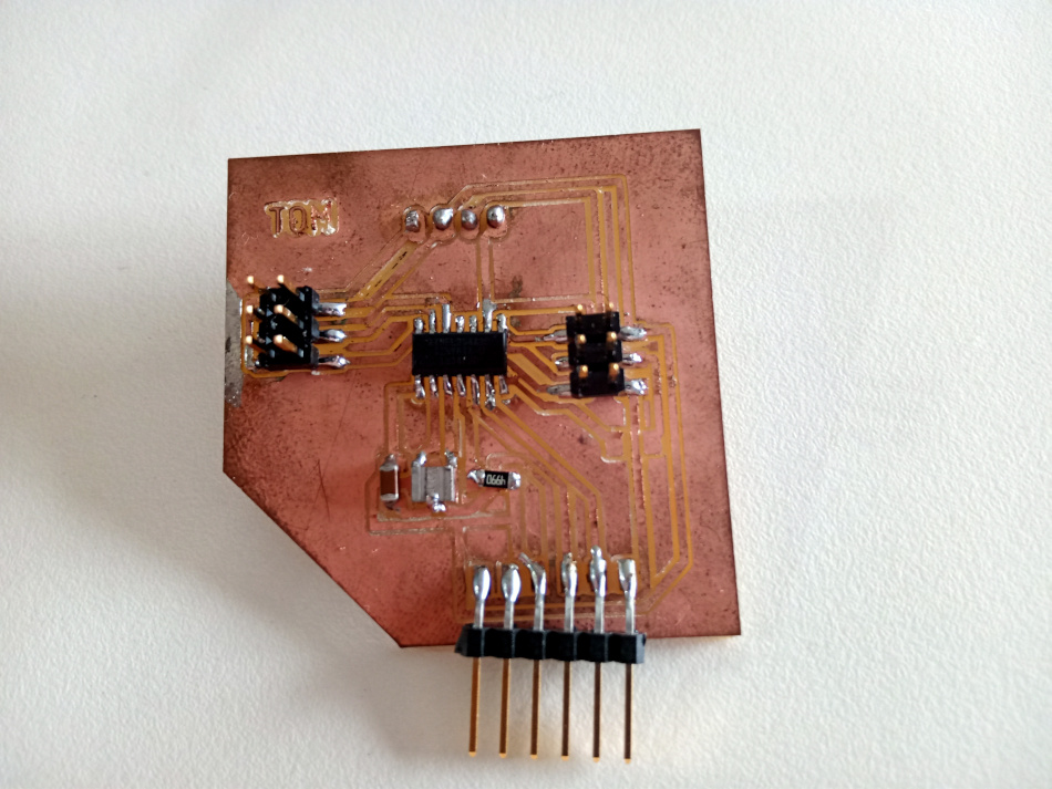
‣ Soldering.
Before starting the soldering process, I washed and dried PCB board to remove any clogged derbies in between traces. I collected and arranged all my electronic components from Fab inventory and kept aside on the workbench. I soldered in all components to board and later checked the continuity using a multimeter.
Looking at my finsihed PCB, I felt the need to improve my soldering skill
‣ Programming the Board.
To program the board I used ARDUINO IDE. I selected my required Board (ATtiny 84 ), Clock (20 MHz) etc and
Burned “ Bootloader”. Everything worked smoothly.
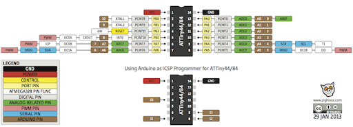
ATtiny 84/44 Pins Out: Since we are using arduino IDE we need to map the change ATtiny 84 pin number with Arduino Pin number. I referred to the data image to understand the pin number.
* Arduino pin 1 is connected to Pin 12 of ATtiny84/44 ( Servo Motor 1 PWM pin connected)
* Arduino pin 2 is connected to Pin 13 of ATtiny84/44 (Servo motor 2 PWM pin connected )
For my first program I used “Servo.h” library to control (sweep) one servo motor.
For my second programming I used "Softwareservo.h" library to control two servo motor.
About servo librariesServo motors are controlled by a series of pulses and to make it easy to use them, an Arduino library has been created so that you can just instruct the servo to turn to a particular angle
Servo.h: This library can control a great number of servos. It makes careful use of timers: the library can control 12 servos using only 1 timer.
Software Servo.h: This Library can drive servos on all of your pins simultaneously.but you must call the SoftwareServo::refresh() method at least once every 50ms or so to keep your servos updating.
Program for controlling One Servo Motor
            #include < Servo.h>

                Servo myservo;  // create servo object to control a servo


                int pos = 0;    // variable to store the servo position

                void setup() {
                  myservo.attach(1);  // attaches the servo on pin 12 of Attiny84 to the servo object
                }

                void loop() {
                  for (pos = 0; pos <= 180; pos += 1) { // goes from 0 degrees to 180 degrees
                    // in steps of 1 degree
                    myservo.write(pos);              // tell servo to go to position in variable 'pos'
                    delay(15);                       // waits 15ms for the servo to reach the position
                  }
                  for (pos = 180; pos >= 0; pos -= 1) { // goes from 180 degrees to 0 degrees
                    myservo.write(pos);              // tell servo to go to position in variable 'pos'
                    delay(15);                       // waits 15ms for the servo to reach the position
                  }
                }
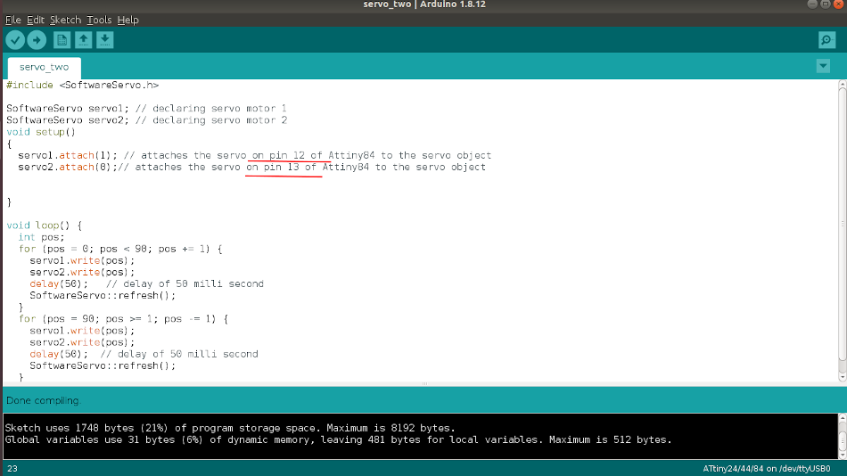
Program for controlling Two Servo motors
#include < SoftwareServo.h>

            SoftwareServo servo1; // declaring servo motor 1
            SoftwareServo servo2; // declaring servo motor 2
            void setup()
            {
              servo1.attach(1); // attaches the servo on pin 12 of Attiny84 to the servo object
              servo2.attach(0);// attaches the servo on pin 13 of Attiny84 to the servo object


            }

            void loop() {
              int pos;
              for (pos = 0; pos < 90; pos += 1) {
                servo1.write(pos);
                servo2.write(pos);
                delay(50);   // delay of 50 milli second
                SoftwareServo::refresh();
              }
              for (pos = 90; pos >= 1; pos -= 1) {
                servo1.write(pos);
                servo2.write(pos);
                delay(50);  // delay of 50 milli second
                SoftwareServo::refresh();
              }
            }
Using my Fab programmer I uploaded both programs and the it worked.
‣ Working Videos
One Servo Motor
Two Servo Motors
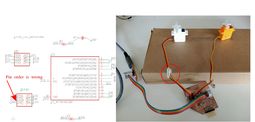
‣ Mistakes
Pinout order of servo motor is (PWM,+5V, GND), but when connecting the ATtiny 84 to ISP pin i wrongly followed servo motor pinout as (+5V, PWM, GND). For rectifying this I swapped two wires of the servo motor,I dont think it's a good approach. I could have used jumper cables instead of cutting wires.
Group assignment:
‣ Measure the power consumption of an output device
Link to week 11- Output week group assignment page